<body leftmargin=0 topmargin=0 marginwidth=0 marginheight=0>


top page, english, japanese


Re-construction cheap lights --

As for cheap lights, LEDs are no good and solders are frail, besides in the generality of cases they're overdriven for showing good even if only slightly. Something so as cheap.

However there are good shells composed shaving alminum and be attractive as an example. As for a shell it's difficult to make impressive one for amateur. It's better to divert or reconstruct shell of manufactured products. e.g. installation a Power LED, flash circuits and so on.

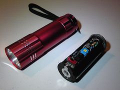
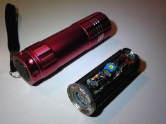
There is a basic battery box for three AAA batteries which is shaped tubular and is used for various lights. That's rating is 4.5V due to three cells and drives white LED which Vf is around 3.0 ~ 3.5V. However three cells are bothered to manage, I planed to use two cells and install a dcdc and a flash circuit into surplus cell space.

As for this box installed circuit few types for bombshell LEDs, a Power LED and so on were created, and as for main frame installed LEDs and a current limiter also few types were created, which could be made use of combination.

At first something dwelt on light.


Cheap Light Re-Constructed Hand-build
30th January 2015
-- dcdc, flash, powerLED into cheap light
 
Policy
 
1. Flash and Consumption
2. Bombshell LED and Power LED
3. Around Charger
 
for Bombshell LED
 
1. Original Product
2. Circuit
3. One Cell Space
4. High Performance
 
install Power LED
 
1. Power LED
2. Circuit
3. Main Frame
4. Power Supply
5. NJM2360AD


Policy


What purpose the flash is, might be almost for a cycle lamp. Even if other purposes, it comes into question to be visibly. For pratical use it's better to keep high visibly and to hold down electric power consumption. In principle, that's possible due to make one flash short and keep current strength for one flash.

For an example, case of same current rating and period 0.3 seconds, it's not so different visibly between flash 0.1 seconds and flash 0.05 seconds though, its electric power consumption ratio would be 2 vs 1.
Flash 0.1 seconds with period 0.3 seconds is better visibly and holds down lower consumption than flash 0.2 seconds with period 0.5 seconds.

Admitting that, it has limitation to make flash time short. Maybe around 0.05 seconds is limitation, which depends on the circuit and its program, voltage, current.

Relaxation Oscillator is none other than the discrete circuit which could control such requisites. As a discrete, it would be only one. Of course it's kinda difficult to control, e.g. it comes to be difficult to keep current strength due to flash too short period. However relaxation oscillator is better by far to be made visibly and lower consumption than vibrator and ring circuits. It would be more accurate to say that vibrator and ring circuits are no good for efficiency.
If it needs to control period and flash time, current and so on, it has no choice but to use AVR or PIC, IC programmabled or to divert IC of ready made products.

This page about "tail lamp" introduces various circuits for cycle tail lamp.


There is no difference as a semiconductor, but difference digits of current ratings, between a bombshell LED and a Power LED.
Depends on the shape, a bombshell LED is more likely to be high directivity e.g. angle cut by half around 15 ~ 30 degrees, a Power LED has no directivity which needs collimator or reflector to make directivity.
A Power LED is normally for high current strength, it needs cooling device essencially. Cooling body is all to use a Power LED which remark is found here and there.
Recently there are high current and high illumination bombshell LED which has thick legs for cooling.

A reason of constant current circuit recommended. A reason of cooling body concerned.
Heat over the maximum rating makes LED to bring degradation and failure. Otherwise heat not over the rating though high heat has possibility to bring some problems. Cause high heat makes Vf of the LED lower, it brings overcurrent to the LED with resistance driven under constant voltage. That brings more heat and makes Vf lower as a vicious cycle. As a matter of a bombshell LED with dozen mA current has no problem with resistance under constant voltage.
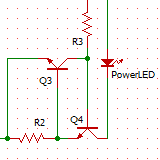
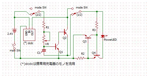
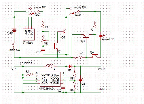
It's enough to use simplistic constant current circuit with two transistors(right picture, A = Vbe / R) instead of high efficient switching power supply. Any constant current circuit should be used for a Power LED.

By the way, there are many constant current LED driver in market with doubtful circuits. Those are not high efficient and have high heat. It's needed to take pains to make the incidental twelve voltage for use such drivers isn't it.


A rechargeble NiMH battery is desirable to be long life. Most important approach is making no degradation due to over discharge though, it's easy to over discharge due to use for light.
Recently there are much lights with a Li-ion battery. A Li-ion with protection circuit would stop to discharge at proper final voltage, i.e. it would not be used at unexpected timing. It's not that no need protection circuit which has a risk to fire and explode due to over discharge.
It's passable and valid to use a NiMH battery for light in guessing, cause elctric density of a NiMH has come to close to a Li-ion's. Besides for hand-build light such a risk should be fended off in guessing.

As for a NiMH there is almost no risk though, its life come to be very short due to over discharge.
As discharge features of a NiMH, voltage drop is very small, when drop of intensity of illumination could be noticed it might be over discharged. Voltage drop of gadget with dcdc could not noticed especially.

In shortpoint it's concern to know the timing for exchange.
It's best to have a battery indicator. It's better to have a monitor lamp turned on in case of closing to the final voltage. Without such items, if it could be exchanged earlier it doesn't make to over discharge. And case of earlier exchange, it's suggested to use a discharger cause continuation charging makes battery memory effect. A discharger will stop at proper final voltage and help to keep battery good condition.
By the way proper final voltage is certain voltage should be stopped with certain load. Proper voltage might be exchange due to impedance of load.
Please refer to this page named "discharger" in depth.


for Bombshell LED


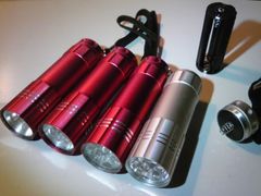
There are three types original products with three bombshell LEDs, five bombshell LEDs and nine bombshell LEDs.

For all types, there is one chip resistor on the basement for LEDs. Values are 3.6ohm for three LEDs, 2.0ohm for five LEDs and 1.2ohm for nine LEDs. Three dry batteries as 4.5V would make them overdrive in case of standard Vf, which would make short runtime and make LEDs degradation. Overdrive is not so high illumination and is wrong efficiency.
In case of three NiMH batteries as 3.6V makes a bit overdrive which is not so extreamely.

Numerical expression for power voltage, Vf and resistor is simple. Normally it's often calculated resistor impedance due to difference between voltages already fixed. If the difference of voltages is large, Current expected would be stable less subject to individual differences of parts. However that would make large electric power consumption of resistor.
I designed contrary and made difference of voltages small, contained electric power consumption of resistor, extended runtime. As for current which might come to be instability, the resistor should be optimized due to not count on theory but try and select. And exchanged LEDs to high performance ones.

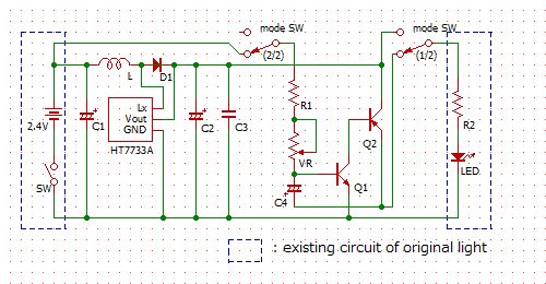
As for dcdc boosted 2.4V two cells to 3.3V due to use HT7733A. The difference between power voltage and Vf would be very small.


A dcdc and a relaxation oscillator. Exchanges constant or flash due to a mode switch. Exchanges period of flash due to hemi fixed resistor.
Multi LEDs connected in parallel.


3. One Cell Space

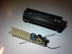
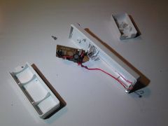
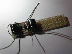
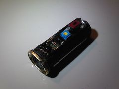
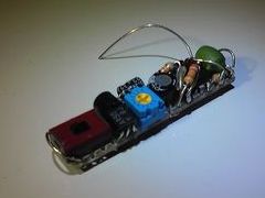
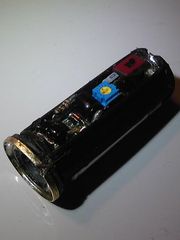
A left picture is a part of the dcdc only on basement. A right picture is the battery box installed that basement added the relaxation oscillator, which could drive lighting efficiently and could flash.

As for a main switch is used original one located the cap which connects minus of battery box and aluminum shell. A metal ring is fitted with bottom of battery box in order to connect GND and the aluminum shell.


As for power supply, the performance is much the same as original one around illumination and runtime. Practically the runtime extended as much x1.5 cause due to two cells compared to original three cells.
The flashing runtime is extream long as a matter of course.


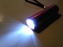
As for left picture, exchanged LEDs to high performance ones and compared original light under same currents.


install Power LED


For using a Power LED, --

- constant current circuit
- high current dcdc
- cooling body
- collimator lenz

Requirements increase.
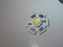
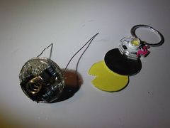
A right picture is a Power LED which is cheap one though it illuminates 200LM by 600mA.

Two AAA NiMH cells are not so powerful. Cause the load would be around 1.0 ~ 1.5W the power supply should be made in anticipation of drop down.
At first tried to divert a dcdc of a charger product for celular which boosts 5.0V with a chip named 8A71.


A constant current circuit with two transistors is adjusted for 600mA maximum rating of the Power LED. Perhaps the dcdc would be its bottle neck, it's no problem without constant current circuit in guessing.
This constant current circuit is mounted to side of the main frame shell.


3. Main Frame

Mounts a constant current circuit on a basement sized same as original one with bombshell LEDs.

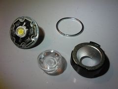
The Power LED would be mounted on another side of that basement which could be compressed with an aluminum plate, an aluminum ring and thermal conduction cement for radiation.

A collimator lenz or a reflector should be mounted.


Temporary tried to turn on lighting by original battery box with three cells.
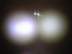
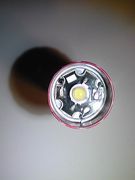
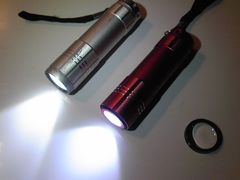
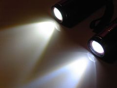
As for a left picture, left one is mounted a reflector and a lenz, right one is mounted a reflector only. As half illuminated angles are around 30 and 60 degrees in guessing.

As for a right picture, left one is mounted a reflector and a lenz, right one is mounted a collimator lenz. The collimator lenz is specified 10 degree.


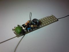
A dcdc and a relaxation oscillator circuit are installed to the battery box.

It had could be made as same scheme as "for bombshell LED" mentioned above due to use the HT7750A though. It couldn't be used cause there was not enough space for indactance for large current. I didn't search parts well though, temporary diverted the dcdc of charger product for celular. The chip was 8A71.


tried to use NJM2360AD for dcdc.


This indactance is not for large current cause small space or neglect of searching parts.


The runtimes were 55minutes for 8A71 and 70minutes for NJM2360AD due to two AAA NiMH batteries 750mAh. Illumination difference between those was not so much.

Illumination predicted by current value was around 100LM, so called 1W class. The main frame stood a large current 200LM / 600mA, wished to make another dcdc for large current.


please post any impressions you may have


e_mail to webmaster