Ended up updating it, it will be 800lm/400lm light.
While experimenting with a constant-current circuit made with an OPamplifier and MOSFET, shown in the next chapter, I wanted to rebuild it. The purpose was twofold as follows:
-- First, to replace it with a slightly more efficient circuit.
-- Second, to allow switching between 400lm and 800lm.
Also, the transistors used in the constant-current circuits of the two transistors have already been disconstructed, and the stock of these transistors is running low.
The fact that both the voltage and resistance, which determine the current value, can be set relatively freely and that MOSFET can be used, offer advantages such as suppression of losses and ease of achieving higher illumination levels.
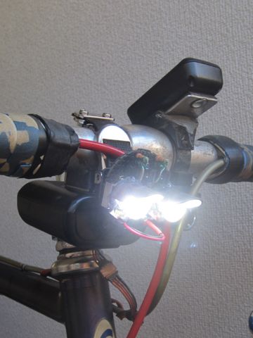
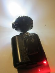
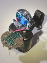
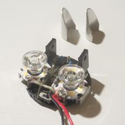
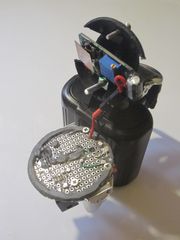
The update does not mean that only the circuitry has been rebuilt, but the entire head section, including the constant current circuit and Power LEDs, has been newly created without changing the power supply section, so it is easy to replace and revert back to the previous version.
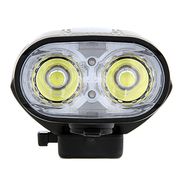
It looks the same as before. The circuit itself has been revamped. The only difference from the diagram in the next chapter is that there is no monitor lamp in the circuit that sets Vref.
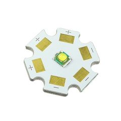
Since the illuminance is different, the LEDs used are different and the values of each parameter (program) are also different.
Incidentally, dcdc is close to its limit. If you try to increase the output of dcdc to increase illumination, the output will drop and oscillation will occur, causing the chip to heat up. I adjusted the output to just before it does not happen.
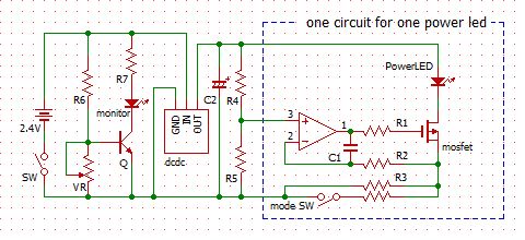
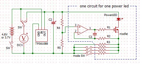
Here is a circuit of the update, including the battery monitor described later.
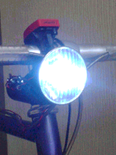
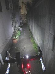
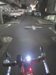
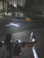
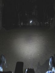
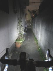
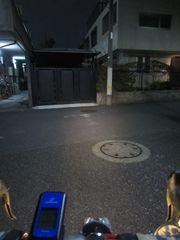
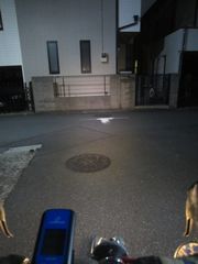
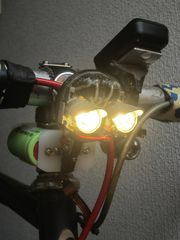
The increased illumination is evident to compared to past images.
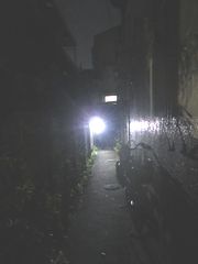
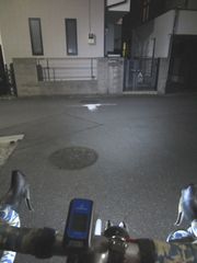
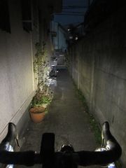
The intensity of light is also impressive in the absence of streetlights.
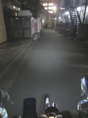
The light would have to be directed downward a bit more to be annoying. As you can see on the wall in the left image, the upward light distribution is cut off by the eaves.
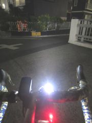
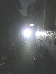
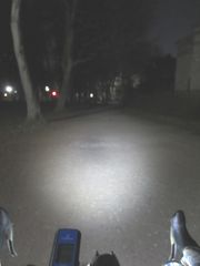
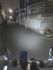
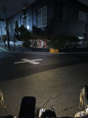
The irradiation light is quite noticeable where streetlights are not so strong (right images).
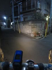
The irradiation light is not so noticeable in brightly lit areas (left images).
It would have to be over 1000lm to do that.
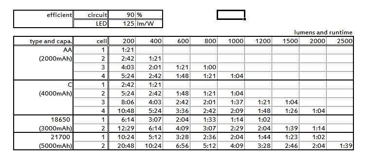
With 800lm it works 1 hour and 15 minutes, and with 400lm it works 2 hours and 15 minutes. Basically, I would use 400lm and switch to 800lm as needed.
I was hoping for a longer runtime at 400lm, but I think this is probably the result of adjusting the dcdc output to somewhere near the limit for this configuration. If I tried to increase the output beyond this, it would start oscillating even with sufficient battery power, and the MT3608 chip would also overheat, which would result in more losses.
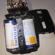
I think 800lm is the limit with two C NiMH rechargeable batteries (2.4V, 4000mAh)
The batteries are two 4000mAh C NiMH rechargeable batteries.
When the power runs out and the voltage drops sharply, the light begins to oscillate. The oscillation is intermittent at first, but if it continues to be used as it is, the oscillation cycle will shorten and the light will become an extremely annoying light pollution light. Stopping the light when it starts to oscillate is very convenient, because the light can be taken out just before it reaches the appropriate termination voltage.
This means it's easy to avoid the risk of using NiMH rechargeable batteries until they are damaged by over-discharge.
Since the head part can be easily replaced, I made the head part as an option.
The cable connections were also made easier to replace using pin connectors, so all I have to do is remove two bolts.
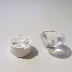
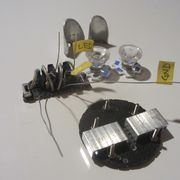
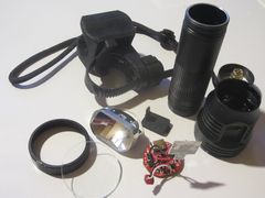
The first head part I made is only backward-compatible, so I don't use it anymore; I disassembled it partly because I missed some parts such as LEDs and collimators, but the circuit parts assembled on the board can only be used for the same purpose.
Those parts were diverted to make a head part with different characteristics as follows:
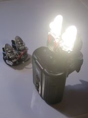
-- Uses light bulb-colored LEDs
-- Low illumination level of 400lm/150lm for longer runtime for long rides.
High-intensity bicycle lights always use cool white LEDs. They do so because they are highly efficient, but that's no fun either.
On brightly lit streets, 150lm is sufficient as long as visibility is maintained. Even on roads without streetlights, 400lm is enough to see the road surface. This might be more practical for street riding.
Due to the compatibility of the LEDs and collimator, the light distribution is narrower than the previous products. However, compared to cool white LEDs, there is no eye-piercing glare.
Mode switching is done for 2 lights individually, so effectively 3 modes of 400lm/275lm/150lm
Runtime is 2 hours 20 minutes with 400lm and 5 hours 30 minutes with 150lm. I'm estimating that with 275lm it would be about 4 hours.
Unfortunately, this circuit does not oscillate when the time comes to change the NiMH rechargeable battery. This is not to say that the circuit will not oscillate, but by the time it does, it will be too late and the NiMH rechargeable battery will have been over-discharged.
Therefore, we incorporated a circuit that turns off the monitor lamp at low voltage (see below).
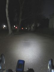
Even without streetlights, there doesn't seem to be any problem with visibility of the road surface.
Of course, its brightness is inferior to 800lm, so if the course has many streets without street lights, it is better to use 800lm head part.
Although irradiation light can be seen under streetlights, it is not very strong.
I guess it's easier to see because the color tone is different from the white LEDs in the streetlights.
Irradiated light is not very noticeable in bright streetlights.
I think it will be positioned as a light for visibility in town driving.
NiMH rechargeable batteries must stop discharging at the appropriate termination voltage. Any further discharge will damage the battery, resulting in loss of capacity and making charging/discharging itself impossible.
When using an 800 lm head part, it would start oscillating as it approached the termination voltage, at which point the battery could be replaced. It was a very convenient phenomenon indeed. The drop down occurs rapidly as it approaches the capacity limit with a certain load.
However, when the optional head part is used, it does not oscillate even when the termination voltage is below the termination voltage. Continued use until oscillation occurs would certainly damage the battery. The difference may be due to the difference in load, but the difference in circuitry seems to be the cause of this difference.
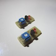
Therefore, a system to monitor the battery was incorporated. If the voltage falls below the specified voltage, the monitor lamp will turn off. The circuit diagram is as follows:
One transistor and two resistors. Simple circuit but fine-tunable and reliable.
The light turns off when the transistor base voltage falls below 0.6V. VR is essential to eliminate the influence of subtle individual differences. Adjust using batteries those have been lowered to terminal voltage with a discharger.
While ordinary battery checkers measure the voltage dropdown with a load of different capacities, this battery monitor is incorporated as the power supply unit of this light, so the load is the light and the battery is monitored when the light is turned on.
There is a multi-cell battery monitor to monitor individual cells, but it is an overkill system to use for such a device.
If you are concerned about the two cells being out of balance, just increase the detected voltage a bit to "take the battery out earlier". Then run them through the discharger individually.
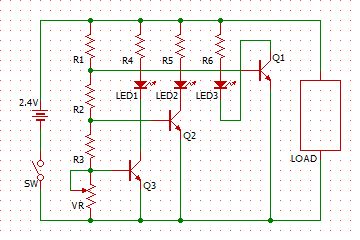
Ideally, three or four LEDs would be arranged in a row and turn off sequentially as the battery is depleted, or use a full-color LED to change hue. A monitor that shows the degree of depletion like that would be good. It would be very good if the remaining usage time could be estimated.
This is because, as a security component, lights cannot be discontinued while riding at night. If I knew I was going on a long ride, I would carry a spare battery, but this is not always possible.
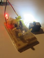
In the circuit diagram on the right, the LEDss turn off in order from LED1 as the battery is depleted, and LED3 also turns off when the termination voltage is reached. Assuming two NiMH cells, R2 and R3 are relatively small resistors, R1 is relatively large, and the VR should be 50 to 60% of R1 when combined with R2 and R3. The timing of turning off LED1 and LED2 is a matter of what level of remaining battery power to close up, and is focused by the values of R2 and R3. It would be possible to estimate the remaining usable time of each of LED1 and LED2 when they are turned off.
It's too much of a hassle to go this far, though (lol).
Personally, I use a small but 100lm sub-light in conjunction with it, so even if I take care of these NiMH rechargeable batteries, no problem with it for city riding.
This small sub-light and the tail light share a battery. I was concerned about the separate batteries for the lights I built this time, and even considered the possibility of having a single, powerful battery to share.
But I thought there was an advantage to having distributed and redundant batteries, since one could be discontinued.
I took the opportunity to add a monitor circuit to the sub-light battery as well.
I would like to make everything from the casing. I want to make it to the exact same specifications so that we can maintain compatibility.
The head part was made for the 1000lm+ light in the next chapter, and it turned out to be unexpectedly skillful. I will make the same thing as this. The shape of the head part is all made according to a unified standard.
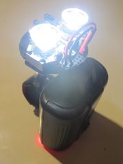
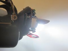
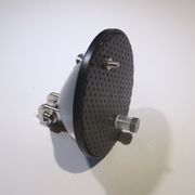
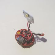
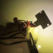
I installed the main circuit of 800lm and the parts where the LEDs will be placed for a test.
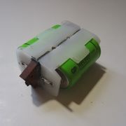
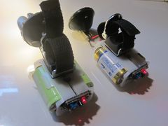
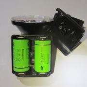
First, I want to make the battery box part compact. Second, I want to make it waterproof.
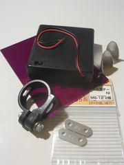
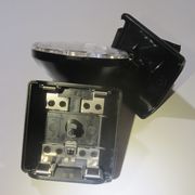
I dared to fit two battery boxes for one battery and embedded switches, nuts for attachments, and other parts in the slight dead space.
I used super glue, but the battery box is a slightly hard material to glue, so I used bolts for all attachments as well as all joints. Maybe the paint won't ride as well.
It would be perfect if it could be covered, but I can't think of a clear way to do it at the moment. Is it possible to bend an acrylic or metal plate to make a removable case?
Surprisingly, this power supply part was more of a hurdle. should I buy a 3D printer?
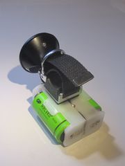
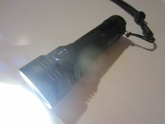
Waterproofing was put on the back burner and the casing was made to be usable as a casing. For the time being, there is no problem unless it is used in the rain. The shape of the casing is almost the same as the one used for HL-300.
I wish I could at least paint it.
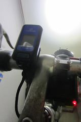
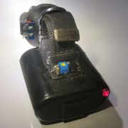
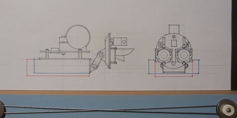
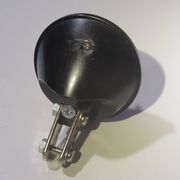
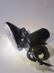
The head is complete when the voltage booster circuit is installed in the head and a monitor lamp is attached to monitor the battery capacity. The light-emitting parts that have already been fabricated can be attached and used.
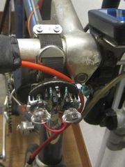
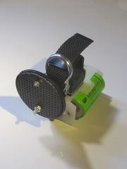
The head part can be turned downward by pushing it from behind. The head angle can be easily adjusted in the same way as that of the HL-300. Furthermore, the height of the light emitting part can be adjusted within a range of several centimeters.
The belt that attaches to the bar is diverted from Soubitez AV-828, Since M4 nut is installed, many things that use bolts can be diverted. Belts of one-coin shop lights can also be diverted.
In fact, two of the same ones were being made at the same time.
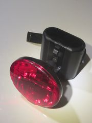
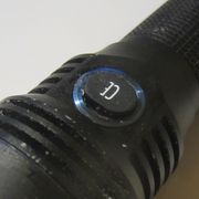
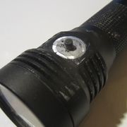
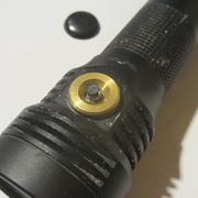
And the monitor lamps look sharp.