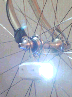
<body leftmargin=0 topmargin=0 marginwidth=0 marginheight=0>


top page, english, japanese


bicycle head lamp

It's a long time since the LED had become a standard, and there are much variations of cycle head lamp in market.

As opportunities due to hand-build, I would tried to introduce something none in market e.g. battery in common used both of head and tail lamp, a Power LED colored same as fairly lamp, possible to exchange period of flash, notification of final voltage of re-chargeble battery, and so on.

I would like to seek after efficiency, e.g. it's not linear relation between visibly and electric power consumption, it depends on various factors time of one flash, period of flash, current value for one flash and so on.

At first something dwelt on light. And I wrote concrete examples in order of newer.


We have made lights with ultra-high luminous intensity, 400, 600 and 800 lumens. Please refer to another page.
It is a very simple circuit without flashing.
This page that you are currently viewing only describes the use of bullet-type LEDs and PowerLEDs of 2W or less. With the spread of lithium-ion rechargeable batteries and electric bicycles, it is becoming commonplace for bicycle lights to have high illumination. Under such an awareness, lights with 100 or 200 lumens may affect visibility.


Hand-build Head Light For Bicycle
since 17th July 2007
--
 
Policy
 
1. Flash and Consumption
2. Bombshell LED and Power LED
3. Around Charger
 
exchange PowerLED of "Small Front"
 
1. Momentum Exchange
2. Circuit
3. Pictures
 
add PowerLED to "Small Front"
 
1. add PowerLED
2. Circuit
3. Pictures
4. Three Cells
 
Small Front
 
1. in Common System
2. divert IC flashing by Open Collector
3. Charge Pump due to Oscillation
4. Pictures
5. Allocation Front and Rear
 
LED to Fairly Lamp
 
1. Policy
2. dcdc and Oscillator
3. Pictures
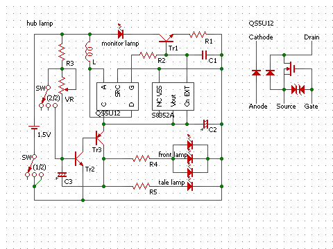
4. Hub Lamp with same circuit


Policy


What purpose the flash is, might be almost for a cycle lamp. Even if other purposes, it comes into question to be visibly. For pratical use it's better to keep high visibly and to hold down electric power consumption. In principle, that's possible due to make one flash short and keep current strength for one flash.

For an example, case of same current rating and period 0.3 seconds, it's not so different visibly between flash 0.1 seconds and flash 0.05 seconds though, its electric power consumption ratio would be 2 vs 1.
Flash 0.1 seconds with period 0.3 seconds is better visibly and holds down lower consumption than flash 0.2 seconds with period 0.5 seconds.

Admitting that, it has limitation to make flash time short. Maybe around 0.05 seconds is limitation, which depends on the circuit and its program, voltage, current.

The relaxation Oscillator is none other than the discrete circuit which could control such requisites. As a discrete, it would be only one. Of course it's kinda difficult to control, e.g. it comes to be difficult to keep current strength due to flash too short period. However relaxation oscillator is better by far to be made visibly and lower consumption than vibrator and ring circuits. It would be more accurate to say that vibrator and ring circuits are no good for efficiency.
If it needs to control period and flash time, current and so on, it has no choice but to use AVR or PIC, IC programmabled or to divert IC of ready made products.

This page about "tail lamp" introduces various circuits for cycle tail lamp.


There is no difference as a semiconductor, but difference digits of current ratings, between a bombshell LED and a Power LED.
Depends on the shape, a bombshell LED is more likely to be high directivity e.g. angle cut by half around 15 ~ 30 degrees, a Power LED has no directivity which needs collimator or reflector to make directivity.
A Power LED is normally for high current strength, it needs cooling device essencially. Cooling body is all to use a Power LED which remark is found here and there.
Recently there are high current and high illumination bombshell LED which has thick legs for cooling.

A reason of constant current circuit recommended. A reason of cooling body concerned.
Heat over the maximum rating makes LED to bring degradation and failure. Otherwise heat not over the rating though high heat has possibility to bring some problems. Cause high heat makes Vf of the LED lower, it brings overcurrent to the LED with resistance driven under constant voltage. That brings more heat and makes Vf lower as a vicious cycle. As a matter of a bombshell LED with dozen mA current has no problem with resistance under constant voltage.
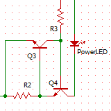
It's enough to use simplistic constant current circuit with two transistors(right picture, A = Vbe / R) instead of high efficient switching power supply. Any constant current circuit should be used for a Power LED.

By the way, there are many constant current LED driver in market with doubtful circuits. Those are not high efficient and have high heat. It's needed to take pains to make the incidental twelve voltage for use such drivers isn't it.


A rechargeble NiMH battery is desirable to be long life. Most important approach is making no degradation due to over discharge though, it's easy to over discharge due to use for light.
Recently there are much lights with a Li-ion battery. A Li-ion with protection circuit would stop to discharge at proper final voltage, i.e. it would not be used at unexpected timing. It's not that no need protection circuit which has a risk to fire and explode due to over discharge.
It's passable and valid to use a NiMH battery for light in guessing, cause elctric density of a NiMH has come to close to a Li-ion's. Besides for hand-build light such a risk should be fended off in guessing.

As for a NiMH there is almost no risk though, its life come to be very short due to over discharge.
As discharge features of a NiMH, voltage drop is very small, when drop of intensity of illumination could be noticed it might be over discharged. Voltage drop of gadget with dcdc could not noticed especially.

In shortpoint it's concern to know the timing for exchange.
It's best to have a battery indicator. It's better to have a monitor lamp turned on in case of closing to the final voltage. Without such items, if it could be exchanged earlier it doesn't make to over discharge. And case of earlier exchange, it's suggested to use a discharger cause continuation charging makes battery memory effect. A discharger will stop at proper final voltage and help to keep battery good condition.
By the way proper final voltage is certain voltage should be stopped with certain load. Proper voltage might be exchange due to impedance of load.
Please refer to this page named "discharger" in depth.


exchange PowerLED of "Small Front"

This chaptor is a continuation of "add PowerLED to "Small Front"" which is also a continuation of "Small Front".
I wrote 'exchange' though made a new part of front.


Two momentums, --

One momentum was a short runtime due to impossible quick flash. Its reason was too long one flash time due to change voltage of battery. It seemed to be able to be adjusted due to exchange a condenser though I took opportunities to exchange all.

Another momentum was to create a light with a Power LED due to One Cell which was very compact and had an intention to divert its head shell to cycle head lamp. That compact light was used one 14500 Li-ion battery which voltage was 3.7V. And the "Small Front" was used batteries 3.6V as same. It's easy to divert withough exchange the circuit.

A Power LED was selected to be colored as same color of a fairly lamp. That reason was just to be rare, recently a LED light were almost colored cool white. There was no different as ratings e.g. lumen.


Drew to divided tail and front.

There is no constant current circuit nor resistor as a current limiter.
Puts the output of the dcdc into a Power LED directly. HT7750A boosts 3.6V of battery to 5.0V. The current is limitted by the indactance. That might be a wrong method though it had worked well. Maybe good efficiency?


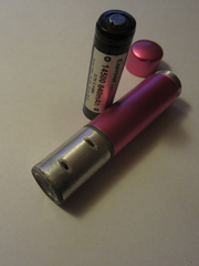
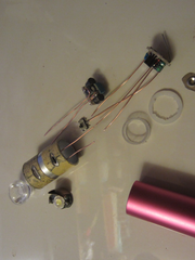
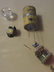
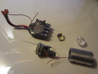
These two pictures were in the making "light with a Power LED due to One Cell".
A pink pipe is a battery holder which is not used for this head lamp.


An aluminum pipe shaved for two levers of switches which wraped by masking tape as a picture.
At reverse side of the pipe there is one hole for inserting a driver which could be adjusted the period of flash due to hemi fixed resistor.


diameter 18mm, length 27mm


Installed a dcdc and a relaxation oscillator, a thermal conduction copper plate, a Power LED, a collimator lenz, a main switch, a mode switch into this aluminum pipe.


Old part for bombshell LEDs is used an atatchment of an adaptor as same as before. There are four LEDs diameter 3mm. Recent high performance LED is very luminous.

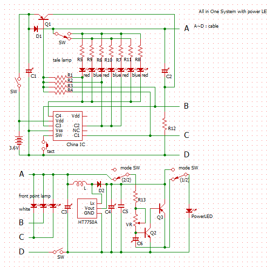
I didn't draw on the diagram though, added a switch 2 circuits 2 positions which could shift a Power LED and a bombshell LEDs due to one motion.
It's possible to turn on both of them due to shift to bombshell side and turn on own switch for a Power LED.


add a PowerLED to "Small Front"

This chaptor is a continuation of "Small Front". Adds a Power LED to the lamp already finished.


Whether an electric bicycle is prevailed or not there are also head lamps with Power LEDs as monadelphous which could illuminate road surface withough street lights. It has come to ordinary circumstance to be used a so-called W class head lamp for a bicycle, Sides to visually recognize has come to think that's ordinary circumstance.
It's disappointed to see that in shopping mall for an example.

Under such a circumstance, it's precarious to have bombshell LEDs only, and decided to add a Power LED. Well, it's also simply that I wished to.

One cable wire added from tail lamp is GND only. New part mounted are a dcdc and a relaxation oscillato, a Power LED, a thermal conduction plate, a collimator lenz, which count of parts is so much though I would make that compact with air flow.

The battery is in common used though a Power LED is used separatively.


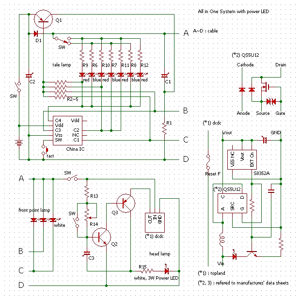
Drew to divided tail and front.

As for a tail lamp, four red LEDs were added and could be shifted to three blue LEDs.
That reason was the battery voltage drop due to constant lighting of a Power LED. And that turned off blue LEDs. When flashing a Power LED it's no ploblem.
A dcdc was diverted from charger for a celular producted by topland.
It's not good to use resistor as a current limiter of a Power LED though there was no space for a constant current circuit.


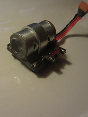
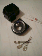
Three bombshell LEDs were inmounted to an atatchment of a holder which would be shaped flat, and a Power LED and its circuit were installed into an acrylic dome as same as before instead of bombshell LEDs.
A cooling body was very small though it had many pins for radiation, thus it would be right with air flow in guessing withought test.


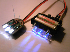
In mode of all LEDs turned on lighting which duty ratio is 25%, tried to shift blue and red LEDs as a right picture. That was before installing a Power LED.


It would got air flow to cut front and rear of the acrylic dome. A collimator lenz stuck out in front of the dome and hemi fixed resistor exposured in rear of the dome.


kinda backward angle.
Half angle of the collimator was 30 degree though lighting was leaking wide angle which would got visibly for wide.


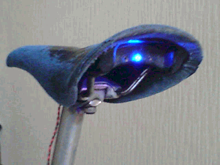
This is a part of a tail lamp which would be inmounted to a saddle.

Exchanged the battery box for two AAA to for three AAA.
It located over side of LEDs.


Blue LEDs would not be turned off while a Power LED was lighting constant.


I wondered when the battery dropped down it's not so wrong cause constant lighting of a Power LED is used rarely only.


One flash lighting had come to be long due to change the voltage of battery. Illumination is enough but it had been impossible to flash quickly and that made runtime to be short.
That could be adjusted due to exchange the condenser or resistors though which had been left.


Small Front

A small front lamp could be made due to make in common system of front and tail lamp. In case of that battery and circuit would be mounted to the tail lamp. Front, around handle, is desired to be neat and clean especially for a roadbike or a sport typed bicycle.

There are many merits due to use the battery and the circuit in common. I had wished to use a security alarm in common though I couldn't find a good shell for it inmounted to a saddle.

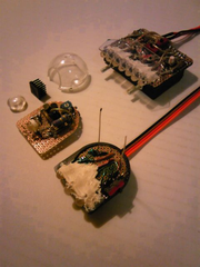
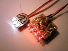
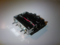
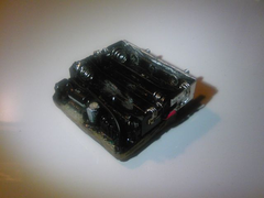
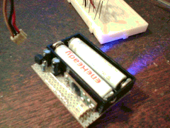
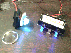
As for a left picture there are parts of a head lamp. It would be most small class one in guessing. The battery and the cicuit would be installed to the unit inmounted to a saddle.
Of course bombshell LEDs could be inmounted to an atatchment or a holder though there is not reason to make so small.

Demerit of that is the cable which should be brought out and be splined in top tube.

Bombshell LEDs could be inmounted to any parts even if it's small part, e.g. a mounter of cycle computer, any belt, a brackets, and so on.
It's might be good to affix a plate mounted high performance LEDs to around head, to make an atatchment for bombshells, and so on.

At the end of consideration, --
I made an atatchment to be mounted to bottom of the belt of a cycle computer. It would be possible to take off and be in the shade. Around the head would be clean too. As for the atatchment, it was already made for another mono-head lamp.


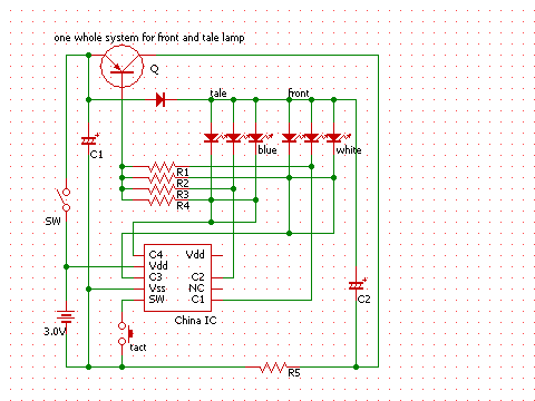
There is a right IC to be diverted which is made in China, and has seven patterns of flash, is used for a cheap tail lamp and toys.
There are two types as old and new. New one has four control lines which is convenience to divide to front and tail. Old one has three control lines in which case it's good to use one line in common of front and tail.

Old and new chips have same count of pins. Old chip has five pins for three control lines, new one has four pins for four control lines and has one NC pin. New one come to stand higher voltage than old one.
Its basement come to be used better material.

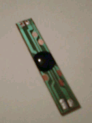
Cut its basement with enough margin as a right picture. It could be cut more small for installation.


Divides control lines to front and rear.
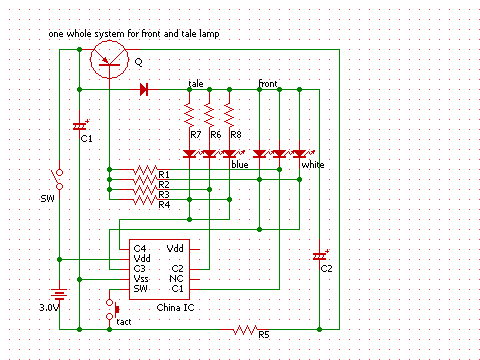
It's aim to charge pump due to oscillation without dcdc circuit, which could turn on lighting white and blue LEDs by two NiMH cells.
Focal points as follows:

- charge pump due to oscillation
- turn on/off due to one motion of a switch
- fixed flash pattern selected
- prevention momentary power off


Cause one flash time is very short by the IC, resistors as current limiter are no need. Its efficiency would be good in guessing.

It might be better to use resistors for blue LEDs. It's a matter of taste though a blue LED has high visibly respect to illumination.


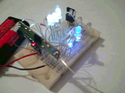
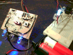
As usual, tested on a breadboard. At first I used a dcdc though, which could not flash as expected. It could not turn off completely. I did investigation of cause, but I couldn't find it.
And I decided to adopt the charge pump method.

As a matter of fact, at the outset I had an intention to use a dcdc cause that's easy and simply. And I changed the plan to design the charge pump used oscillation. Thus I couldn't test the circuit on a breadboard well.


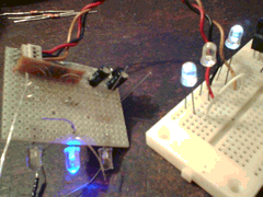
On a basement checked.


Cut the basement kinda larger than battery box and mounted some parts on it.


It needs a cable with three wires and put a connector on it. Three wires are for Vdd and two collector control lines.


It could be used as mono-tail lamp without cable to the front lamp.


Heaped LEDs of a front lamp. It's interesting that the flash lighting is moving ups and downs.


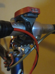
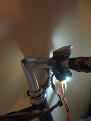
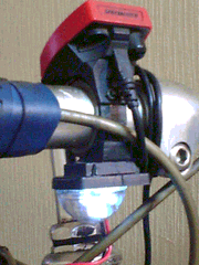
Set the front lamp as a right picture.


The light set to an atatchment mounted on bottom of a holder of a cycle computer. That's small and in shade.


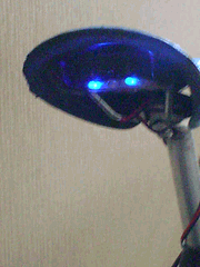
As for an acrylic dome, it has visibly for side angle lower illumination though.


A tail lamp inmounted to a saddle.


Flashing due to momentary lighting is so pretty.


this way. Installed resistors for blue LEDs of a tail lamp.


A blue LED is easy to secure visibly respect to its illumination.

Resistors as current limiter of a tail lamp would make electric power margin for a head lamp, cause charge pump due to oscillation. That's efficiency in guessing.
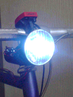


LED to Fairly Lamp


I had a favorite fairly lamp and an intention to install LEDs without reconstruction but atatchments.
It used two C batteries. I found the adaptor AA to C which could be inmounted a dcdc and a oscillation circuit.
LEDs would be ready as an atatchment mounted them to a bracket of a fairly lamp.

C battery has enough capacity which could drive long time even if one cell.


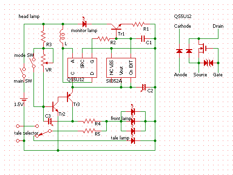
A relaxation oscillator for flash would be made as descrete.
A dcdc was diverted from a charger for celular.
It's ideal to set resistors for each LED individually though, Only one resistor was set for them cause the small spacing. Terminal for output to a tail lamp were fixed that's out of policy though.
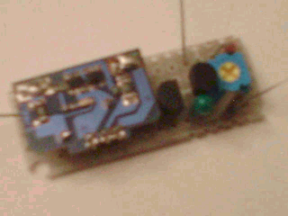
R4 and R5 were brought out normally though, R4 was inmounted and R5 was mounted outside.

As for a mode SW, it's an illegal method for constant lighting. That might be wrong efficiency for constant lighting though, constant lighting was rarely used but flash lighting as mainly.
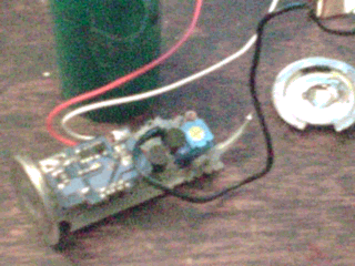


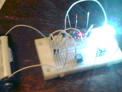
Tested on breadboard.


I used transistors for strobe which could make stronger flash than e.g. 1015/1815, which could be tested on a breadboard easy.
Voltages could be used for the relaxation oscillator are 1.2V of the cell and 4.8V of the dcdc output. Illumination of flash would be exchanged due to values of condensers and resistors, which should be tested well. For an example, quick flash would be impossible to raise up too much illumination of flash, that's posed a dilemma.

Tried to test under a battery droped down.


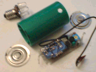
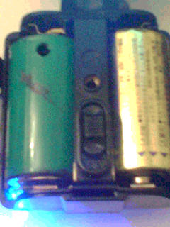
A green pipe was the adaptor AA to C. Installed circuits and put a lid on.
A hole of it for put in a driver which could adjust the period of flash due to turn around a hemi fixed resistor.

Upper left parts of the picture was LEDs with a bracket of a fairly lamp.

A black wire is used in common GND with the battery.


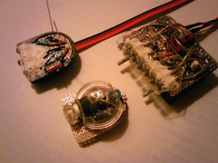
A core part as a right picture.


Red and white wires brought out to a mode switch, which could be took off easy due to a connector.


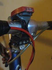
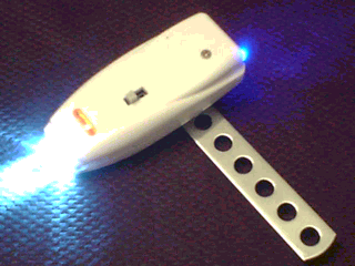
A same picture as top of this page.

A left green pipe is the adaptor which circuits are inmounted, and its hole put in a driver could adjust the period of flash.
A right one is a C dry battery, instead of which a C NiMH rechargeble battery could be used.


A tail lamp due to bring out the cable.


Used a switch with 2 circuits 3 positions.


A shell was diverted from a charger for celular.

Sized 35 x 77 x 18mm.
Weighted 25g plus 15g arm and 25g AA battery.

This shell was ABS resin, which cover closed by screw.
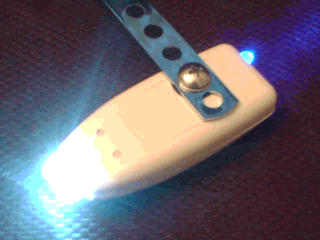
Holes of the arm was used to be fixed to the hub.


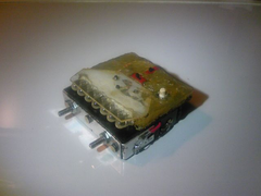
Back side as a right picture.


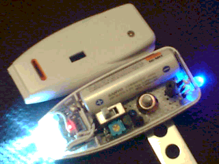
Took off the cover.

A switch has three positions.

A volume under the switch could adjust the period of flash due to +driver.

A battery is an AA NiMH rechargeble battery. As 2,000mAh its runtime was only several hours for constant lighting and was few hundred hours for flash lighting with period around 0.3 seconds. Flash lighting runtime depended on the period of flash.

That's so so good as one cell.


As for a hub lamp it's located too low position that's not good for visibly, thus I had not used...


please post any impressions you may have


e_mail to webmaster